Abstract: A circuit is shown that senses the temperature of a remote thermal diode on the die of a CPU, FPGA, GPU, or other high-performance IC. When the thermal diode temperature exceeds a pre-defined trip point, a cooling fan switches on, thereby providing a simple fan control function.
Cooling fans are common in PCs, workstations, and other systems that can generate significant heat during normal operation. In many such systems, however, cooling isn't needed 100% of the time. In these systems, it is preferable to operate the fan only when cooling is needed, rather than full time. Operating the fan only when needed increases fan lifetime and reduces system noise.
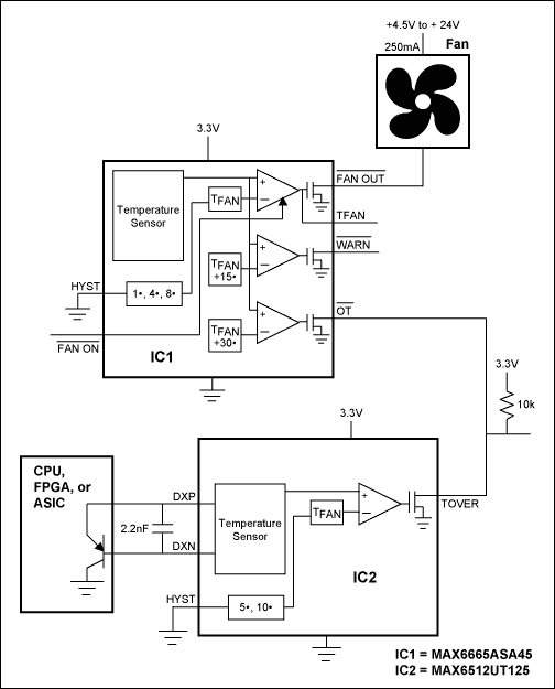
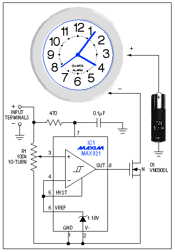
The circuit shown below uses a very simple, low-cost approach to controlling a fan's operation based on the die temperature of a microprocessor, FPGA, or other high-power chip. The target IC must have a temperature-sensing PN junction (typically the base and the emitter of a substrate PNP) available. The circuit is based on a MAX6513 remote temperature switch (IC1). IC1 forces current with precisely controlled ratios through the sense junction on the target IC, measures the junction's forward voltage at each current, and calculates the temperature of the remote junction based on this information. If the measured temperature exceeds the factory-programmed threshold temperature, the MAX6513's output pin (TOVER) goes active, turning on the N-channel MOSFET and supplying power to the fan.
The threshold temperature can be chosen to match the needs of the target IC. In the circuit shown here, IC1 has a threshold of 55°C. Typical values for fan control range from about 45°C to about 65°C, but higher values can also be accommodated. After activating the fan, hysteresis keeps the fan on until the temperature drops 10°C below the trip temperature. If 5°C hysteresis is preferred, connect the HYST pin to ground. For best results, locate IC1 close to the target IC and keep high-speed digital traces away from the DXP and DXN traces to avoid noise coupling.

Figure 1. This simple fan controller activates the fan when the temperature of the target IC exceeds 55°C.

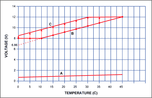
Figure 2. The fan turns on when the trip temperature is exceeded. Temperature has to fall below the trip temperature minus the hysteresis before the fan turns off. By connecting the HYST pin to ground or VCC, 5°C or 10°C hysteresis can be selected.
Cooling fans are common in PCs, workstations, and other systems that can generate significant heat during normal operation. In many such systems, however, cooling isn't needed 100% of the time. In these systems, it is preferable to operate the fan only when cooling is needed, rather than full time. Operating the fan only when needed increases fan lifetime and reduces system noise.
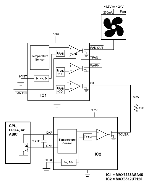
The circuit shown below uses a very simple, low-cost approach to controlling a fan's operation based on the die temperature of a microprocessor, FPGA, or other high-power chip. The target IC must have a temperature-sensing PN junction (typically the base and the emitter of a substrate PNP) available. The circuit is based on a MAX6513 remote temperature switch (IC1). IC1 forces current with precisely controlled ratios through the sense junction on the target IC, measures the junction's forward voltage at each current, and calculates the temperature of the remote junction based on this information. If the measured temperature exceeds the factory-programmed threshold temperature, the MAX6513's output pin (TOVER) goes active, turning on the N-channel MOSFET and supplying power to the fan.
The threshold temperature can be chosen to match the needs of the target IC. In the circuit shown here, IC1 has a threshold of 55°C. Typical values for fan control range from about 45°C to about 65°C, but higher values can also be accommodated. After activating the fan, hysteresis keeps the fan on until the temperature drops 10°C below the trip temperature. If 5°C hysteresis is preferred, connect the HYST pin to ground. For best results, locate IC1 close to the target IC and keep high-speed digital traces away from the DXP and DXN traces to avoid noise coupling.

Figure 1. This simple fan controller activates the fan when the temperature of the target IC exceeds 55°C.

Figure 2. The fan turns on when the trip temperature is exceeded. Temperature has to fall below the trip temperature minus the hysteresis before the fan turns off. By connecting the HYST pin to ground or VCC, 5°C or 10°C hysteresis can be selected.
 德赢Vwin官网
App








评论